2d pen plotter
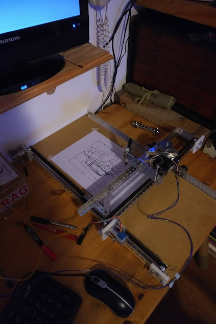
In 2018, I decided to make a 2d pen plotter. Pen plotters are a bit like printers, but rather than drawing images pixel by pixel by raster scanning, they instead move a pen around to draw things.
The build
Rails and carriages
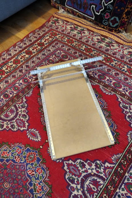
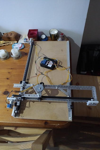
I decided to follow the time-honored design of having two axis movement by virtue of a carriage that moves in one axis, that is itself the tracks for a second carriage, that moves perpendicularly to the first.
With limited tools, and only a small flat to build in, I decided to use model makers pre-drilled aluminium angle. This work work for the rails, and also for other elements of the frames.
I screwed to pieces of angle to a piece of hardboard I found in a cupboard (which therefore arbitrarily set the demensions of the plotter), and then bolted the rest of the angle together. Luckily the aluminium was easy to cut with my little hacksaw.
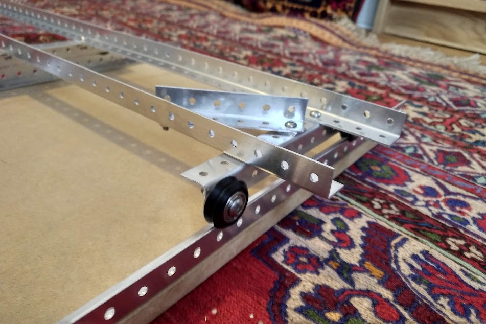
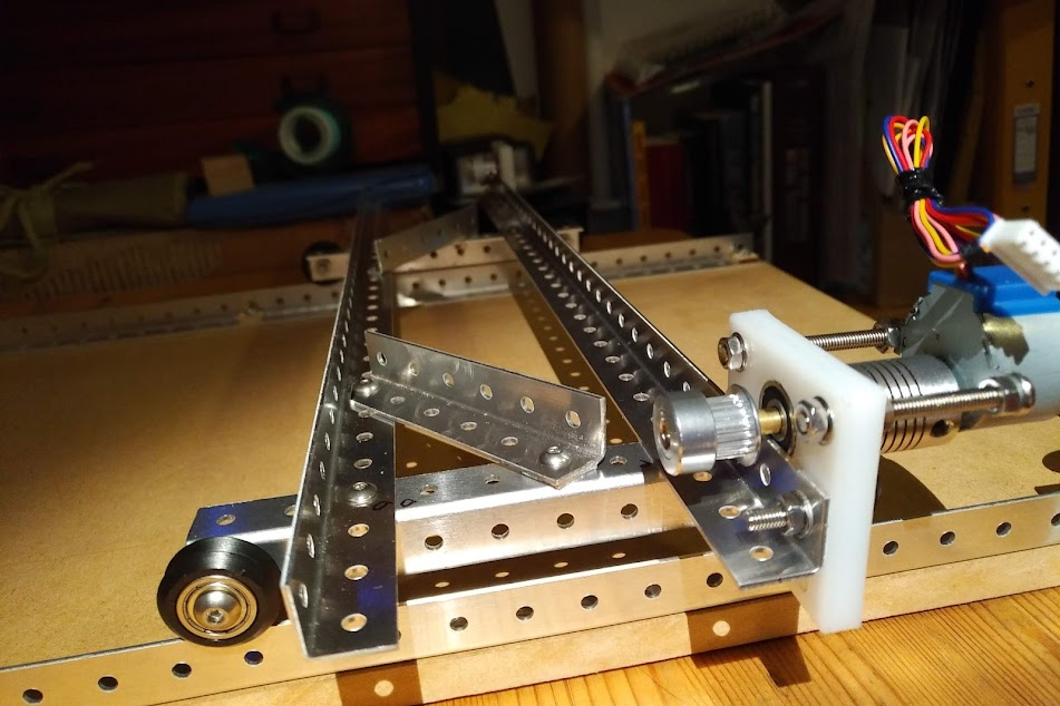
For the wheels that ran on the rails, I used 3d printer pulleys, which have a V groove, perfect for running on the rails, and readily available off ebay.
Stepper motors
To drive the carriages, I bought some cheap stepper motors of ebay, and a dual stepper motor control board that would be driven by my raspberry Pi. The motors were mounted using some bits of a plastic chopping board, with appropriate holes drilled, including for a bearing to support a brass shaft that was couple to the motor via a little shaft coupler (also from ebay). On the other end of the shaft I mounted a toothed pulley wheel, also designed for 3d printers.
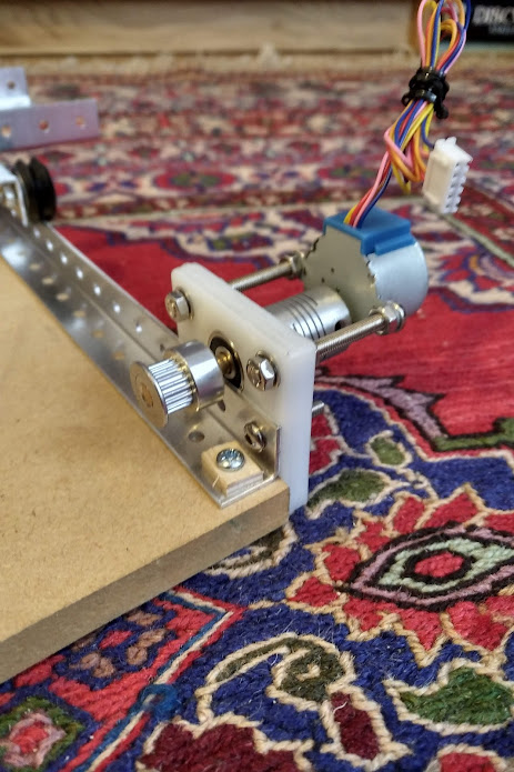
A second stepper motor was similarly mounted on rails that move on the first axis, thereby powering movement of the carriage that would hold the pen.
Belt drives
The drive from the stepper motor was transfered to the carriages by toothed belts. These were simply tensioned with a nut and bold, and attached to the thing they had to move via a small length of aluminium angle.
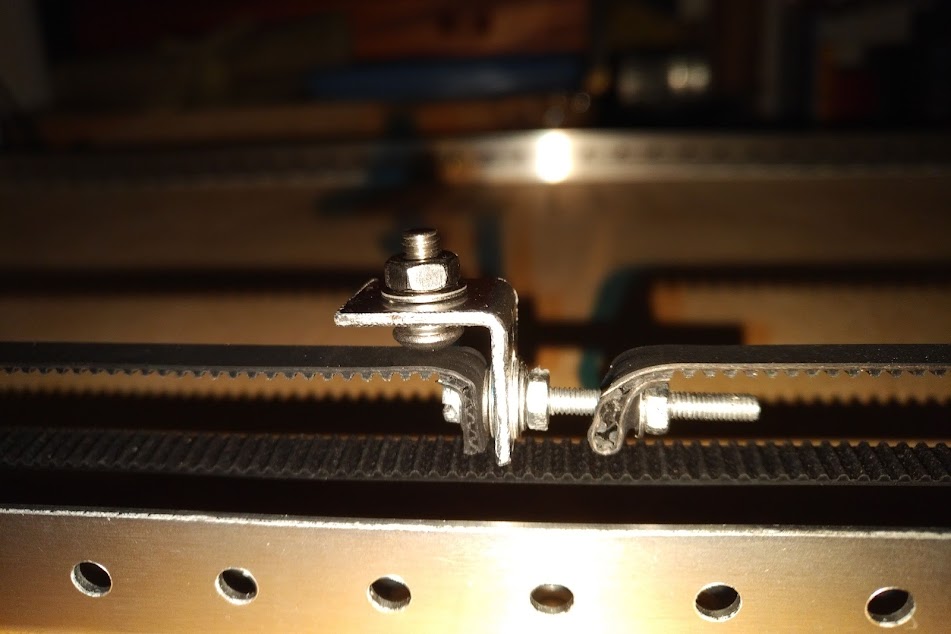
With both belts in place, the plotter now could move in two axes.
Drawing
The last stage of the hardware was the pen. This was simply a sharpie clamped to a "nodding donkey" arrangement, consisting hinged piece of aluminium angle. The pen could be lifted up using a servo (controlled by the pi), and gravity could drop the pen on to paper.
I wrote some Python code that would control the stepper motors in such a way that I could feed in coordinates, and the plotter would move the pen to follow them. Coupled with instructions to lift or lower the pen, this was inprinciple all that was needed to draw things.
I generated the coordinates to follow from vector images using InkScape. You can save inscape images in a format that was used for old-school plotters (I think called .hpgl), which is just a list of coordinates, with other instructions.
I wrote a script to read these files, and pass on the isntructions to the plotter. I also wrote a script to visualise the results of plotting these coordinates, so I could check that things looked right.
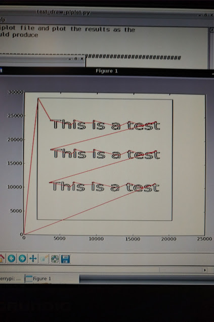
And that was pretty much it. The whole thing worked first time. It was very slow, but did the job. I did find that occasionally the stepper motors would slip and miss a step. There was no feedback telling the raspberry Pi where the pen was, so the plotter essentialy was just working blind and had no idea where it was.